


BLOG
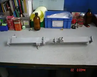
What materials are used in constructing Water-Cooled Twist Waveguides?
March 4, 2025
Water-cooled twist waveguides represent a crucial advancement in high-power microwave transmission systems, combining sophisticated materials engineering with precision cooling technology. The primary materials used in constructing these specialized waveguides include high-conductivity oxygen-free copper (OFHC) for the main waveguide body, electroformed copper for intricate internal structures, and high-grade aluminum alloys for external cooling channels. These materials are specifically chosen for their excellent thermal conductivity, superior electrical performance, and resistance to corrosion. The construction also incorporates specialized brazing alloys for joining components and high-performance polymer seals for water channel integrity. Each material plays a vital role in ensuring optimal electromagnetic transmission while maintaining thermal stability under high-power conditions.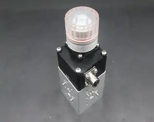
How does a Waveguide Electromechanical Switch work?
March 4, 2025
A Waveguide Electromechanical Switch is a sophisticated microwave component that enables controlled switching of electromagnetic waves between different waveguide paths. These switches operate through a precise mechanical mechanism actuated by electromagnetic forces, allowing for the selective routing of microwave signals. The switch typically consists of a movable conducting element within the waveguide structure that can be positioned to either permit or block wave propagation along specific paths. When activated, the electromagnetic actuator moves this conducting element to redirect the microwave energy with minimal signal loss and exceptional isolation between ports.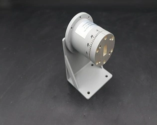
How does a 90° Polarized Rotary Joint differ from a regular rotary joint?
March 4, 2025
Understanding the distinctive characteristics of specialized microwave components is crucial for engineers and system designers working in high-frequency applications. Among these components, rotary joints play a vital role in maintaining signal integrity across rotating interfaces. This article explores the key differences between 90° Polarized Rotary Joints and standard rotary joints, highlighting their unique features, applications, and benefits in various industries. A 90° Polarized Rotary Joint represents a specialized variant of rotary joints designed specifically to maintain polarization orientation during rotation. Unlike regular rotary joints that simply transfer RF energy between stationary and rotating parts, 90° Polarized Rotary Joints incorporate advanced design elements to preserve the 90-degree polarization angle of electromagnetic waves throughout rotation. This critical capability ensures signal integrity in applications where polarization stability is paramount, such as satellite communications, radar systems, and advanced telecommunications infrastructure, making 90° Polarized Rotary Joints indispensable for maintaining optimal performance in demanding rotating microwave systems.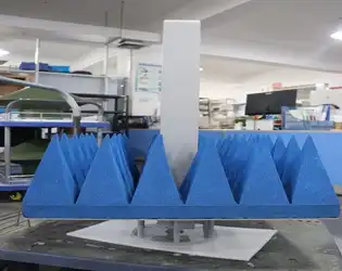
How to measure the performance of a near field measurement probe?
March 3, 2025
In the realm of microwave technology and antenna engineering, accurately assessing the performance of measurement equipment is paramount to ensuring reliable system operation. The Antenna Near Field Measurement Probe represents one of the most critical tools in this field, serving as the foundation for precise electromagnetic field characterization. This blog post explores the methodologies, critical parameters, and best practices for evaluating the performance of near field measurement probes, providing engineers and technicians with comprehensive guidance to optimize their measurement systems.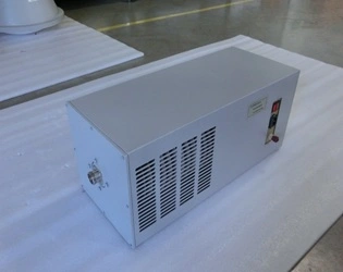
What is the role of a coaxial load in RF and microwave systems?
March 3, 2025
In the complex world of radio frequency (RF) and microwave engineering, every component plays a crucial role in ensuring system integrity and performance. Among these critical components, the Coaxial Load stands as an essential element that often doesn't receive the attention it deserves. Coaxial loads are fundamental devices designed to absorb and dissipate excess RF energy without reflecting it back into the system. This seemingly simple function is vital for maintaining the stability, accuracy, and longevity of RF and microwave systems across various applications including telecommunications, defense, aerospace, and scientific research.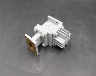
How does power handling capacity affect the design and application of waveguide isolators?
March 3, 2025
Power handling capacity is a critical parameter that significantly influences both the design principles and practical applications of waveguide isolators in microwave systems. As transmission requirements grow increasingly demanding across various industries, understanding the relationship between power handling capabilities and isolator performance becomes essential. High Power Waveguide Isolators are specialized components engineered to manage substantial power levels while maintaining signal integrity in microwave transmission systems. These critical devices protect sensitive equipment by preventing reflected power from returning to the source, effectively creating a one-way path for electromagnetic waves. The power handling capacity directly impacts material selection, thermal management strategies, and ultimately determines the operational limits and reliability of the isolator in real-world applications.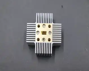
February 28, 2025
The relationship between a waveguide pressure window's thickness and its power-handling capacity is a critical consideration in microwave system design. When examining this relationship, we find that thicker pressure windows generally offer higher power-handling capabilities due to their enhanced structural integrity and improved heat dissipation characteristics. However, this relationship isn't strictly linear – there's an optimal thickness range that balances power handling with signal transmission efficiency. As a crucial component in waveguide systems, the pressure window must maintain its structural integrity while allowing microwave energy to pass through with minimal loss, making the thickness-to-power relationship a key design consideration for high-performance applications.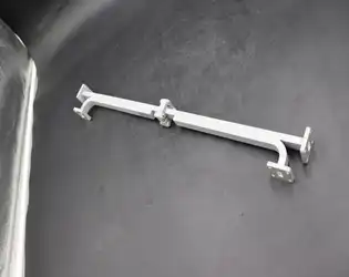
February 28, 2025
The length of the coupling section plays a crucial role in determining the performance characteristics of a broadwall directional coupler. This fundamental parameter directly affects the coupling coefficient, directivity, and overall efficiency of the device. In broadwall directional couplers, the coupling section length typically spans multiple wavelengths and significantly influences the bandwidth, coupling strength, and phase relationships between the coupled and through ports. The optimization of this length is essential for achieving desired coupling levels while maintaining high directivity across the operating frequency range. Understanding these relationships is crucial for engineers and designers working with microwave systems, particularly in applications requiring precise power sampling and monitoring.