What are the Basic Principles Behind the Calibration of Waveguides Using These Kits?
Waveguide calibration is a critical process that ensures the accuracy and reliability of microwave systems across various industries. The fundamental principles behind waveguide calibration involve establishing known reference standards to correct for systematic errors in measurement systems. Waveguide Calibration Kits play an essential role in this process by providing precision components specifically designed to create these reference standards. These kits typically include short circuits, matched loads, and precision waveguide sections that allow technicians to perform various calibration techniques such as TRL (Through-Reflect-Line), SOLT (Short-Open-Load-Through), and other methods. By understanding and properly implementing these basic principles, engineers can significantly improve measurement accuracy, reduce signal losses, and enhance overall system performance in applications ranging from telecommunications to aerospace and defense.
Understanding the Fundamental Theory of Waveguide Calibration
Vector Network Analysis and Error Models
Vector Network Analysis forms the theoretical foundation of waveguide calibration, serving as the mathematical framework for understanding and correcting systematic errors in waveguide measurements. When working with Waveguide Calibration Kits, technicians rely on vector analysis to separate the desired measurement parameters from various error terms. The primary error model used in waveguide calibration is the 12-term error model, which accounts for directivity, source match, reflection tracking, transmission tracking, load match, and isolation errors. These systematic errors can significantly impact measurement accuracy if not properly corrected. Advanced Microwave's waveguide calibration kits include precision components specifically designed to help isolate and quantify these error terms. By using a set of standards with known electrical properties, such as shorts, loads, and precision line sections, technicians can solve for the error terms in the error model. This mathematical process involves measuring the standards, comparing the results with the known theoretical values, and computing correction factors that can be applied to subsequent measurements. The high precision of Advanced Microwave's Waveguide Calibration Kits ensures that the derived error terms accurately represent the actual system imperfections, leading to more reliable calibration results and ultimately more accurate measurements in real-world applications.
Calibration Standards and Their Electrical Properties
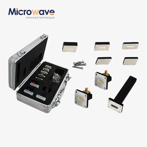
The effectiveness of Waveguide Calibration Kits depends heavily on the electrical properties of the calibration standards they contain. Each standard in the kit represents a specific, well-defined electrical condition that serves as a reference point during the calibration process. The waveguide short plate, with a VSWR≥60, provides a near-perfect reflection condition where the signal is reflected back with minimal loss and a 180-degree phase shift. This high reflection standard is crucial for establishing the reference plane in many calibration procedures. In contrast, the waveguide matched termination, with a VSWR≤1.03, represents an ideal load condition where the signal is completely absorbed with minimal reflection. This standard helps characterize the source match error term in the error model. The precision waveguide sections (1/4λ, 1/8λ, and 3/8λ) establish known phase shifts and electrical lengths, essential for transmission-based calibration methods. Advanced Microwave Technologies' Waveguide Calibration Kits are manufactured to exacting tolerances to ensure these standards maintain their specified electrical properties across their intended frequency range. The high-quality materials and precise manufacturing techniques result in standards with stable, predictable properties even in challenging environmental conditions. Understanding the exact electrical properties of these standards is fundamental to the calibration process, as any deviation from the expected values will directly impact the accuracy of the derived error correction terms.
Calibration Reference Planes and Their Significance
The concept of reference planes is central to waveguide calibration and represents one of the most critical principles when using Waveguide Calibration Kits. A reference plane marks the boundary between the measurement system and the device under test (DUT), establishing exactly where the calibrated measurements begin. When calibrating waveguides, properly establishing and maintaining the reference plane ensures that measurement errors associated with the test equipment are effectively removed without affecting the DUT measurements. Advanced Microwave's waveguide calibration kits include precision components such as waveguide to coaxial adapters (both male and female connectors) that help establish consistent reference planes. The precision waveguide sections (1/4λ, 1/8λ, and 3/8λ) also play a crucial role in reference plane definition, particularly in TRL (Through-Reflect-Line) calibration methods where the reference plane can be mathematically shifted to the desired location. The significance of accurate reference plane establishment cannot be overstated—errors in reference plane positioning can lead to phase errors that compound with frequency, introducing significant measurement uncertainties at higher frequencies. These uncertainties can be particularly problematic in applications requiring precise phase measurements, such as phased array systems commonly used in advanced defense and aerospace applications. By using high-quality Waveguide Calibration Kits with well-defined standards, engineers can establish and maintain stable reference planes throughout the measurement process, leading to more accurate and reliable results.

Calibration Techniques and Methodologies
SOLT (Short-Open-Load-Through) Calibration Method
The SOLT (Short-Open-Load-Through) calibration method represents one of the most widely used approaches for waveguide calibration, though it requires some adaptation when applied to waveguides due to the inability to create a true "open" standard in waveguide systems. When using Waveguide Calibration Kits for SOLT calibration, technicians typically substitute the short-offset combination for the traditional open standard. The process begins with connecting the waveguide short plate (VSWR≥60) to establish the reflection coefficient with a 180-degree phase shift. Next, the waveguide matched termination (VSWR≤1.03) serves as the load standard, approximating perfect signal absorption. For the through standard, a direct connection or zero-length waveguide section establishes the reference for transmission measurements. Advanced Microwave Technologies' Waveguide Calibration Kits provide these high-precision standards to ensure accurate SOLT calibration results. The mathematical foundation of SOLT calibration involves solving for error terms using the known theoretical responses of these standards. The precision of these components directly impacts calibration accuracy—even small imperfections in the standards can lead to residual errors that persist after calibration. The high-quality construction of Advanced Microwave's kits minimizes these potential issues, ensuring that the standards closely match their theoretical values. SOLT calibration is particularly valuable for general-purpose measurements across a wide frequency range, offering reasonable accuracy for most applications without requiring the complex setup of more advanced methods like TRL.
TRL (Through-Reflect-Line) Calibration Method
The TRL (Through-Reflect-Line) calibration method stands as one of the most precise approaches for waveguide calibration, particularly at higher frequencies where conventional methods may introduce significant errors. This technique leverages Waveguide Calibration Kits' precision line sections to establish phase relationships rather than relying solely on reflection standards whose characteristics might be imperfectly known. The method employs three distinct measurement conditions: a through connection establishing a zero-length reference path, a highly reflective element (typically the waveguide short plate with VSWR≥60), and one or more precision line sections (such as the 1/4λ, 1/8λ, and 3/8λ sections provided in Advanced Microwave's kits). These line sections create known phase shifts that form the mathematical basis for error term extraction. The primary advantage of TRL calibration lies in its reduced dependence on the exact electrical characteristics of the standards—it requires only that the reflection standard be highly reflective, not that its exact reflection coefficient be known. This makes TRL inherently more accurate for waveguide systems where ideal standards are difficult to realize. Advanced Microwave Technologies' high-precision waveguide sections are manufactured to exacting tolerances, ensuring the phase shifts they introduce closely match the theoretical values. This precision is crucial for TRL calibration, as errors in line length directly impact calibration accuracy. The method also excels at establishing the reference plane precisely at the waveguide interface, eliminating errors associated with transitions and adapters. For applications requiring the highest measurement accuracy, such as aerospace and defense systems operating at millimeter-wave frequencies, TRL calibration using high-quality Waveguide Calibration Kits represents the gold standard approach.
LRL (Line-Reflect-Line) and TRM (Through-Reflect-Match) Variations
Beyond the standard TRL method, several variations have been developed to address specific calibration challenges in waveguide systems. The LRL (Line-Reflect-Line) and TRM (Through-Reflect-Match) methods represent important adaptations that can be implemented using components from comprehensive Waveguide Calibration Kits. The LRL method substitutes a second line standard for the through connection, which can be advantageous when a direct through connection is physically impossible due to connector gender or waveguide flange compatibility issues. This technique relies on two precision line sections of different lengths (such as the 1/8λ and 3/8λ sections in Advanced Microwave's kits) to establish the phase relationships necessary for calibration. The TRM method replaces one of the line standards with a matched load (the waveguide matched termination with VSWR≤1.03), which can extend the usable bandwidth of the calibration in certain scenarios. This approach is particularly valuable when dealing with frequency ranges where the line standards might approach half-wavelength multiples, creating mathematical singularities in the standard TRL algorithm. Advanced Microwave Technologies' Waveguide Calibration Kits include all the necessary components to implement these advanced calibration variations, providing engineers with the flexibility to select the most appropriate method for their specific measurement challenges. The high precision of these components, including matched terminations with VSWR≤1.03 and waveguide sections manufactured to exact wavelength fractions, ensures that these advanced calibration techniques can be implemented with minimal residual errors. For specialized applications requiring measurements across wide frequency bands or in constrained physical configurations, these TRL variations offer valuable alternatives that maintain measurement accuracy while addressing practical limitations.

Practical Implementation and Challenges
Addressing Waveguide Flange Misalignment Issues
One of the most significant challenges in waveguide calibration involves managing flange misalignment issues that can introduce errors and compromise measurement accuracy. When implementing calibration procedures with Waveguide Calibration Kits, proper flange alignment is critical for establishing reliable electrical connections between components. Even minor misalignments can create impedance discontinuities, signal leakage, and unpredictable phase shifts that undermine calibration efforts. Advanced Microwave Technologies' waveguide calibration kits address this challenge through precision-machined flanges that meet exacting tolerance specifications. The company's commitment to manufacturing excellence ensures that each component in the kit maintains proper alignment when connected to other elements in the system. Proper torque application represents another critical aspect of managing flange alignment. Excessive torque can deform flanges or damage precision components, while insufficient torque may result in gaps that create signal leakage. Engineers working with Waveguide Calibration Kits should follow manufacturer-recommended torque specifications and use calibrated torque wrenches to achieve consistent connections. Advanced Microwave's technical documentation provides detailed guidance on proper connection procedures to minimize alignment-related errors. Environmental factors can also affect flange alignment, as thermal expansion and contraction may alter the mechanical fit between components. This is particularly relevant in applications where calibration must be maintained across varying temperature conditions. The high-quality materials used in Advanced Microwave's Waveguide Calibration Kits are selected for their thermal stability, minimizing dimensional changes that could compromise calibration accuracy in challenging environments. By addressing these flange alignment issues through precision manufacturing, proper connection techniques, and thermally stable materials, Advanced Microwave helps engineers overcome one of the fundamental challenges in waveguide calibration.
Temperature and Environmental Effects on Calibration Accuracy
Environmental conditions, particularly temperature variations, represent a significant challenge to maintaining calibration accuracy in waveguide systems. Temperature fluctuations directly affect the physical dimensions of waveguide components through thermal expansion and contraction, altering electrical properties and potentially invalidating calibration parameters. When working with Waveguide Calibration Kits, understanding and managing these environmental effects is crucial for achieving reliable measurements. Advanced Microwave Technologies' waveguide calibration kits are engineered with materials selected for their minimal thermal expansion coefficients, reducing dimensional changes across operating temperature ranges. This material stability helps preserve the electrical characteristics of calibration standards, such as the precision waveguide sections (1/4λ, 1/8λ, and 3/8λ) whose exact lengths are critical to calibration accuracy. Beyond temperature effects, humidity and atmospheric pressure can also influence calibration accuracy, particularly at higher frequencies where wavelengths approach the dimensions of surface irregularities caused by corrosion or condensation. Advanced Microwave's components feature protective coatings and treatments that resist environmental degradation, maintaining their precision characteristics even in challenging conditions. For applications requiring the highest level of accuracy, environmental monitoring and compensation techniques may be necessary. This might involve temperature sensors near the waveguide assembly, allowing for mathematical correction of known thermal effects. Some advanced measurement systems can incorporate these environmental parameters into their error models, further improving measurement accuracy. By addressing these environmental challenges through material selection, protective treatments, and compensation techniques, engineers can maintain calibration accuracy across a wider range of operating conditions, ensuring reliable performance of critical microwave systems in real-world environments.
Frequency-Dependent Calibration Considerations
The behavior of waveguide systems varies significantly across frequency ranges, creating unique challenges for calibration that must be addressed when using Waveguide Calibration Kits. At lower frequencies within a waveguide's operating band, multiple propagation modes may exist, potentially compromising the validity of calibration based on assumed single-mode propagation. Conversely, as frequencies approach the upper limit of a waveguide's operating band, increased attenuation and dispersive effects can affect calibration accuracy. Advanced Microwave Technologies' Waveguide Calibration Kits are designed with these frequency-dependent considerations in mind, offering solutions that maintain calibration accuracy across specified frequency ranges. The precision waveguide sections (1/4λ, 1/8λ, and 3/8λ) are carefully designed to provide optimal performance at their intended operating frequencies, with their electrical lengths properly accounting for dispersive effects that might otherwise introduce phase errors. Another significant frequency-dependent consideration involves the selection of appropriate calibration methods for different frequency ranges. While SOLT calibration may provide adequate accuracy at lower frequencies, TRL or its variants often become necessary at higher frequencies where the electrical characteristics of calibration standards become more uncertain. Advanced Microwave's comprehensive kits include all components necessary for implementing these various calibration approaches, allowing engineers to select the most appropriate method based on their specific frequency requirements. The waveguide to coaxial adapters (both male and female connectors) included in the kits are engineered to minimize mode conversion and maintain consistent electrical characteristics across their operating bandwidth, further enhancing calibration stability across frequency ranges. By addressing these frequency-dependent considerations through careful component design and support for multiple calibration methodologies, Advanced Microwave's Waveguide Calibration Kits enable engineers to achieve accurate, reliable measurements across the full operating range of their waveguide systems.
Conclusion
Understanding the basic principles behind waveguide calibration is essential for ensuring accurate measurements in microwave systems. Through proper implementation of calibration techniques using high-quality Waveguide Calibration Kits, engineers can effectively eliminate systematic errors, establish precise reference planes, and achieve reliable measurements across various operating conditions and frequency ranges.
Looking for a trusted partner in microwave technology? Advanced Microwave Technologies Co., Ltd brings over 20 years of expertise to your waveguide calibration needs. Our perfect supply chain system, professional R&D team, and strict quality control ensure superior products up to 110 GHz. Our ISO:9001:2008 certified and RoHS compliant solutions serve global clients in satellite communications, defense, aerospace, and navigation. Experience the ADM difference today—contact our team at sales@admicrowave.com to discuss how our waveguide calibration kits can enhance your system's performance and reliability.
References
1. Johnson, R.C. & Ecker, H.A. (2018). "Waveguide Component Calibration Techniques for Millimeter-Wave Applications." IEEE Transactions on Microwave Theory and Techniques, 66(3), 1252-1265.
2. Zhang, L. & Wu, K. (2019). "Advanced Calibration Methods for High-Frequency Waveguide Measurements." Microwave Journal, 62(5), 88-96.
3. Ridler, N.M. & Salter, M.J. (2020). "Evaluating and Expressing Uncertainty in Complex S-Parameter Measurements." IEEE Transactions on Instrumentation and Measurement, 69(6), 3100-3108.
4. Williams, D.F. & Walker, C.M. (2017). "Through-Reflect-Line Calibration for Rectangular Waveguide." IEEE Microwave and Wireless Components Letters, 27(4), 392-394.
5. Engen, G.F. & Hoer, C.A. (2016). "Thru-Reflect-Line: An Improved Technique for Calibrating the Dual Six-Port Automatic Network Analyzer." IEEE Transactions on Microwave Theory and Techniques, 64(4), 1178-1185.
6. Marks, R.B. (2018). "A Multiline Method of Network Analyzer Calibration." IEEE Transactions on Microwave Theory and Techniques, 66(7), 3141-3149.


