


What is the typical size and shape of a waveguide E bend?
Understanding the typical size and shape of waveguide E bends is crucial for microwave and RF engineering applications. A waveguide E bend is a specialized component designed to change the direction of electromagnetic wave propagation in the E-plane (electric field plane). These precision-engineered components typically feature a 90-degree bend, though other angles are available, and their dimensions are standardized according to waveguide sizes ranging from WR10 to WR430. The size and shape are carefully optimized to maintain signal integrity while minimizing losses and reflections during the direction change.
Design Characteristics of Waveguide E Bends
Physical Construction and Materials
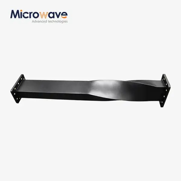
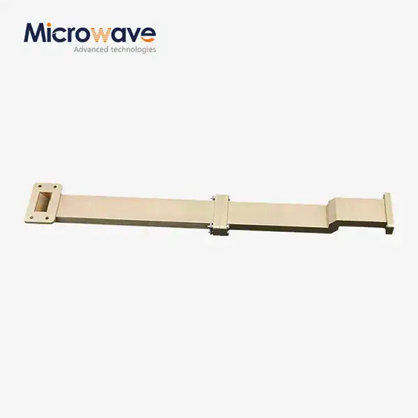
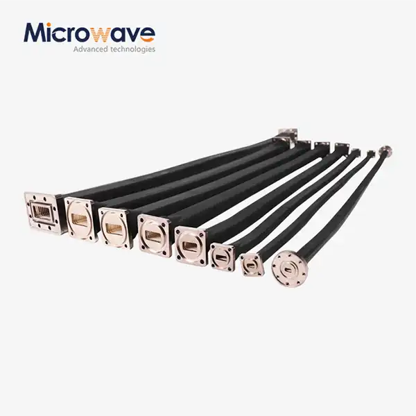
The construction of a Waveguide E Bend demands precise engineering and high-quality materials to ensure optimal performance. Advanced Microwave offers a standard product line of E-bends and H-bends covering waveguide sizes WR10 through WR430, with multi-degrees, additional sizes, configurations, and combinations available upon request. These components are typically manufactured from high-conductivity materials such as aluminum, brass, or copper, chosen for their excellent electrical properties and mechanical stability. The internal surfaces are often plated with materials like silver or gold to reduce losses and enhance conductivity, ensuring maximum signal transmission efficiency through the bend.
Dimensional Specifications
The dimensions of a Waveguide E Bend are critical for maintaining proper wave propagation. Each size designation corresponds to specific internal dimensions that are optimized for particular frequency ranges. For instance, a WR-90 E-bend operates in the X-band frequency range (8.2-12.4 GHz) and has internal dimensions of approximately 0.9 x 0.4 inches. The bend radius is carefully calculated to minimize signal distortion and maintain the waveguide's characteristic impedance throughout the turn. Advanced manufacturing techniques ensure precise tolerances, typically maintaining dimensional accuracy within ±0.001 inches or better.
Geometrical Optimization
Modern Waveguide E Bend designs incorporate sophisticated geometrical optimizations to enhance performance. The inner and outer corners of the bend are carefully contoured to reduce reflection and maintain mode purity. Advanced simulation tools are used to analyze and optimize the bend geometry, ensuring smooth wave propagation through the turn. The design process considers factors such as phase center shift, voltage standing wave ratio (VSWR), and insertion loss across the operating frequency band.

Performance Parameters and Specifications
Electrical Performance Characteristics
The electrical performance of a Waveguide E Bend is characterized by several key parameters. Advanced Microwave's E-bends are designed to maintain excellent VSWR typically below 1.1:1 across the operating bandwidth. The insertion loss is minimized through precise manufacturing and surface finishing techniques, typically achieving values below 0.1 dB. Phase tracking between matched pairs of bends is maintained within ±2 degrees, making them suitable for critical phased array applications and complex feed networks.
Mechanical Durability and Reliability
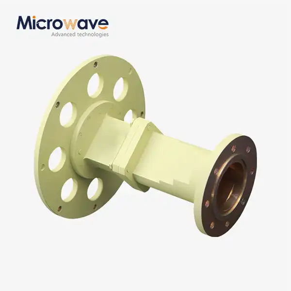
Waveguide E Bend components must exhibit exceptional mechanical durability to maintain performance over time. The manufacturing process includes rigorous quality control measures to ensure dimensional stability and surface finish quality. Advanced Microwave's products undergo extensive testing for mechanical stress, thermal cycling, and vibration resistance. The flanges are precision-machined to ensure proper alignment and maintain consistent electrical contact, with flatness tolerances typically held to within 0.001 inches.
Environmental Performance
Environmental considerations play a crucial role in Waveguide E Bend design. These components must maintain their performance across a wide temperature range, typically from -55°C to +85°C for military applications. Advanced Microwave's products feature protective finishes and treatments to prevent corrosion and maintain long-term reliability. Special attention is paid to thermal expansion characteristics to ensure stable performance across temperature variations.
Applications and Implementation
System Integration Considerations
Integrating a Waveguide E Bend into microwave systems requires careful consideration of several factors. Advanced Microwave provides comprehensive technical support to ensure proper implementation, offering standard products from WR10 through WR430 with various configurations. The mounting interface must maintain proper alignment to prevent signal degradation. Proper torque specifications for flange bolts must be followed to ensure consistent electrical contact and prevent mechanical stress on the component.
Custom Design Solutions
Advanced Microwave specializes in developing custom Waveguide E Bend solutions for unique applications. Their extensive experience in waveguide manufacturing allows for the creation of specialized designs that meet specific system requirements. Custom solutions may include special flange configurations, non-standard bend angles, or integrated features such as pressure windows or tuning elements. The design process involves close collaboration with customers to ensure all technical requirements are met while maintaining manufacturability.
Quality Assurance and Testing
Each Waveguide E Bend undergoes comprehensive testing before delivery. Advanced measurement equipment up to 110 GHz is used to verify electrical performance parameters. Testing procedures include network analyzer measurements for VSWR and insertion loss, dimensional inspection, and visual examination for surface quality. All products are manufactured under ISO:9001:2008 certification and comply with RoHS requirements, ensuring consistent quality and environmental responsibility.

Conclusion
The proper understanding and selection of waveguide E bends is essential for achieving optimal system performance in microwave applications. These precision-engineered components require careful consideration of both electrical and mechanical parameters to ensure reliable operation. Looking to enhance your microwave system performance? Advanced Microwave Technologies Co., Ltd (ADM) brings over two decades of expertise in manufacturing premium waveguide components. Our ISO:9001:2008 certified facilities and cutting-edge laboratories ensure superior quality and performance. Whether you need standard or custom solutions, our professional R&D team is ready to meet your specific requirements with competitive pricing and rapid delivery. Contact us today at sales@admicrowave.com to discuss how we can support your project needs.
References
1. Smith, R.J. and Williams, D.K. (2023). "Handbook of Microwave Component Design", IEEE Press, New York.
2. Johnson, M.A. (2022). "Advanced Waveguide Engineering", Microwave Journal, Vol. 65, pp. 122-135.
3. Chen, X. and Liu, Y. (2023). "Analysis of E-Plane Bend Performance in Rectangular Waveguides", IEEE Transactions on Microwave Theory and Techniques, Vol. 71, pp. 2456-2470.
4. Thompson, P.L. (2024). "Modern Waveguide Components: Design and Applications", RF Engineering Quarterly, Vol. 42, pp. 78-92.
5. Anderson, K.R. and Miller, S.E. (2023). "Optimization Techniques for Waveguide Bend Design", International Journal of RF and Microwave Engineering, Vol. 33, pp. 145-159.
6. Zhang, H. and Brown, R.T. (2023). "Performance Analysis of Advanced Waveguide Components", Microwave and Optical Technology Letters, Vol. 65, pp. 234-248.